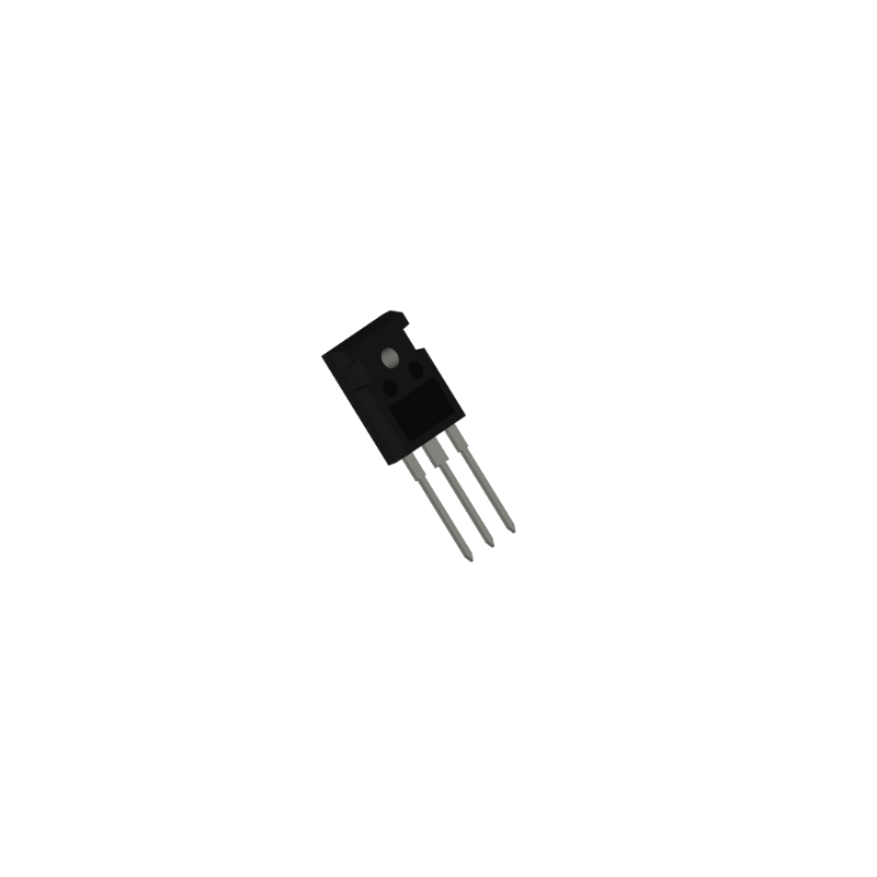
IXFX20N120P
N-Channel MOSFET with 1.2KV Vds and 20A Id packaged in PLUS247-3
Inventory:9,426
- 90-day after-sales guarantee
- 365 Days Quality Guarantee
- Genuine Product Guarantee
- 7*24 hours service quarantee
-
Part Number : IXFX20N120P
-
Package/Case : TO247-3
-
Brands : IXYS
-
Components Categories : Single FETs, MOSFETs
-
Datesheet : IXFX20N120P DataSheet (PDF)
The IXFX20N120P is a high-performance IGBT (Insulated Gate Bipolar Transistor) designed for use in power electronics applications. This IGBT features low conduction and switching losses, making it suitable for high switching frequency applications such as motor drives, renewable energy systems, and power supplies. (Note: The pin configuration below is a general representation. Refer to the specific datasheet for precise details.) Include a circuit diagram illustrating the connections and operation of the IXFX20N120P IGBT for a visual representation. Note: For detailed technical specifications, please refer to the IXFX20N120P datasheet. Functionality The IXFX20N120P IGBT is designed to provide high-speed switching and efficient power regulation in applications where low conduction and switching losses are crucial for overall system performance. Usage Guide Q: What is the maximum collector current for the IXFX20N120P? Q: Can the IXFX20N120P be used in high-power renewable energy systems? For similar functionalities, consider these alternatives to the IXFX20N120P:Overview of IXFX20N120P
Pinout
Circuit Diagram
Key Features
Application
Frequently Asked Questions
A: The IXFX20N120P is capable of handling a maximum collector current as specified in the datasheet. It is important to operate the IGBT within its rated current limits for optimal performance and reliability.
A: Yes, the IXFX20N120P is suitable for use in power inverters for renewable energy applications such as solar and wind power, where high switching frequencies and low losses are required for efficient power conversion.Equivalent
Specifications
The followings are basic parameters of the part selected concerning the characteristics of the part and categories it belongs to.
| Drain-Source Voltage (V) | 1200 | Maximum On-Resistance @ 25 ℃ (Ohm) | 0.57 |
| Continuous Drain Current @ 25 ℃ (A) | 20 | Gate Charge (nC) | 193 |
| Input Capacitance, CISS (pF) | 11100 | Thermal resistance [junction-case] (K/W) | 0.16 |
| Configuration | Single | Package Type | TO-247 PLUS |
| Power Dissipation (W) | 780 | Maximum Reverse Recovery (ns) | 300 |
| Sample Request | Yes | Check Stock | Yes |
Warranty & Returns
Warranty, Returns, and Additional Information
-
QA & Return Policy
Parts Quality Guarantee: 365 days
Returns for refund: within 90 days
Returns for Exchange: within 90 days
-
Shipping and Package
Shipping:For example, FedEx, SF, UPS, or DHL.UPS, or DHL.
Parts Packaging Guarantee: Featuring 100% ESD anti-static protection, our packaging incorporates high toughness and superior buffering capabilities.
-
Payment
For example, channels like VISA, MasterCard, UnionPay, Western Union, PayPal, and more.
If you have specific payment channel preferences or requirements, please get in touch with our sales team for assistance.

IXKR25N80C
Three-pin N-channel MOSFET with 800V and 25A rating

IXFN80N50P
MOSFET with a 500V voltage rating and a maximum current capacity of 66A

IXFX120N20
200V, 120A MOSFET

IXTK120N25P
120 Amp N-Channel Transistor with 250V Voltage Rating and TO-264AA Housing

IXFH44N50P
44A, 500V N-channel transistor with TO-247AD packaging

IXFB100N50P
High-power N-channel MOSFET with 3+Tab Pin Configuration

IXTP96P085T
Metal-oxide Semiconductor FET, P-Channel, 96A Drain Current, 85V Voltage, 0.013ohm On-State Resistance, TO-220AB Housing

IXTN110N20L2
SOT227B-packaged single transistor module engineered for 200V operation and 100A current handling

IXTP80N10T
MOSFET with 80 Amps and 100V, featuring a Rds of 13.0 for high performance

IXTA10P50P
Ready to Ship within 1 Day

