Understanding the TEENSY 3.2 Development Board Pinout
 Prof. David Reynolds
Published:April 26, 2024
TEENSY development boards are popular for small projects, catering to hobbyists, small robot designers, and creators of entertainment setups. One such board is the TEENSY 3.2 Development Board from PJRC(other boards such as Teensy LC, Teensy 3.5, and Teensy 3.6.). This board, compatible with breadboards, is a USB development board of the K20 Sub-Family featuring a 32-bit ARM Cortex-M4 microcontroller unit for implementing various prototypes and designs. Operating at a central processing speed of 72 MHz, it also includes I2S for high-quality audio interfacing and a touch sensor interface. Understanding the pinout of the TEENSY 3.2 development board is crucial for effectively utilizing its features and capabilities. The pinout diagram provides valuable information about the functions of each pin, enabling developers to connect external components and peripherals correctly. This article offers a comprehensive guide to the TEENSY 3.2 pinout, covering its pin diagram, pin configuration, functions, and applications in detail. Whether you're a beginner seeking to learn about development boards or an experienced developer aiming to harness the capabilities of TEENSY 3.2, this article will help you understand how to utilize Teensy 3.2 effectively.
Overview of TEENSY 3.2 Development Board
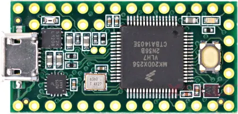
The Teensy 3.2 is a 32-bit Arduino-compatible development board designed to provide ARM Cortex processing power in a format suitable for use with breadboards, ideal for hobbyists. Despite its small size, it offers impressive performance, outperforming the similarly sized Arduino Nano in most aspects. The TEENSY 3.2 is an upgraded version of the TEENSY 3.1, featuring double the Flash memory capacity. Despite its small size, the TEENSY 3.2 is powerful, housing the MK20DX256VLH7 microcontroller unit. It boasts 34 GPIO pins and communication ports for serial data transmission. However, only 24 GPIO pins are accessible without soldering, while the remaining pins require soldering connections, as indicated on the backside of the TEENSY 3.2 development board. The board is energy-efficient and supports a wide range of input power supplies. Overall, the TEENSY 3.2 is simple, easy to use, and offers impressive performance for a variety of hobbyist projects.
Other Development Boards: Arduino, STM32, ESP12, ESP31, Raspberry Pi, ESP8266
Related Read: STM32 vs. ESP8266
TEENSY 3.2 Development Board Pinout
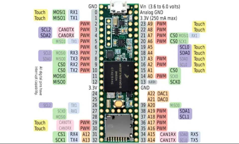
Teensy 3.2 Pin Diagram
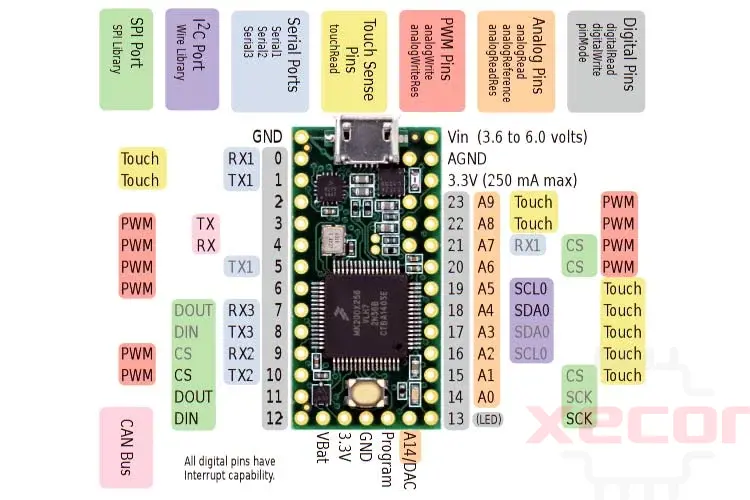
The diagram below illustrates the pinout of the TEENSY 3.2 Development Board from the front end:
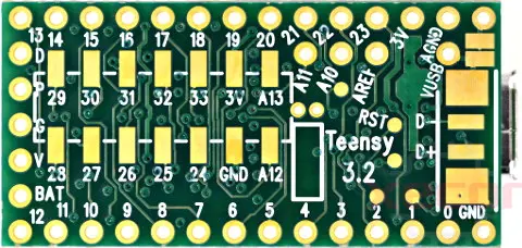
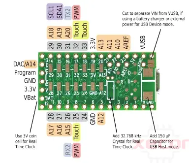
The diagram below displays the pinout diagram of the TEENSY 3.2 from the back side:
Teensy 3.2 Pin Configuration
|
Pin Category |
Pin Name |
Details |
|
Power |
VIN, 3.3V, Analog GND, GND |
VIN – Supply voltage pin when using an external power source (3.6V to 6.0V) 3.3V – Regulated output voltage from the on-board regulator (250mA max.) Analog GND – Acts as GND for the ADC and DAC, can be connected to GND GND – Ground pins |
|
Analog Pins |
A0 – A9, A14 |
Pins A0 – A9 and A14 can act as analog inputs with 13-bit resolution |
|
Input/output pins |
D0 – D23 |
24 I/O pins breadboard friendly |
|
Serial |
TX1, RX1 TX2, RX2 TX3, RX3 |
3 serial ports |
|
External interrupts |
D0 – D23 |
All digital pins have interrupt capability |
|
PWM |
D3 – D6 D9 –D10 |
22 PWM pins total |
|
SPI |
DIN, DOUT, SCK, CS |
SPI port |
|
Inbuilt LED |
D13 |
LED to act as a general-purpose GPIO indicator |
|
I2C |
SCL0, SDA0 |
Inter-Integrated Circuit communication port |
|
CAN |
TX, RX |
CAN bus ports |
|
Touch sensing |
D0 – D1 D15 – D19 D22 – D23 |
Can be used for capacitive touch sensing |
Digital Pins
Digital Input Pins
Digital pins on the Teensy 3.2 can receive signals. By default, these pins are turned off for low power. To configure them for input mode, use the pinMode function with INPUT. Then, you can read the input using digitalRead. The Teensy 3.2 pins accept signals from 0 to 5V and are 5V tolerant. Do not drive any digital pin higher than 5V.
Input Pullup & Pulldown Resistors
All digital pins have optional pullup and pulldown resistors. These resistors are used to keep the pin at logic HIGH or logic LOW when it is not actively driven by external circuitry. Typically, these resistors are used with pushbuttons and switches. To configure these pins for input mode with the built-in resistor, use the pinMode function with INPUT_PULLUP or INPUT_PULLDOWN.
Pin Change Interrupts
All digital pins can detect changes. Use attachInterrupt to run a function when a change is detected automatically. Interrupts should only be used for clean signals. The Bounce library is recommended for detecting changes in pushbuttons, switches, and signals with noise or mechanical chatter.
Digital Output Pins
All digital pins on the Teensy 3.2 can act as output pins. Use the pinMode function with OUTPUT or OUTPUT_OPENDRAIN to configure these pins for output mode. Use the digitalWrite and digitalToggle functions to control the pins while in output mode. The output HIGH level is 3.3V, and the recommended maximum output current is 10mA.
Pulse Width Modulation (PWM)
12 of the digital pins on the Teensy 3.2 support Pulse Width Modulation (PWM). PWM can be used to control motor speed, dim lights, and LEDs or for other applications where rapid pulsing can control average power. Use the analogWrite function to control PWM. The PWM frequency can be controlled for 3 groups of PWM pins using the analogWriteFrequency function.
Slew Rate Limiting
This optional feature on the Teensy 3.2 greatly reduces high-frequency noise when long wires are connected to digital output pins. It slows the rate of voltage change on the pin, which can help reduce undesirable high-frequency effects that can cause issues with long wires.
LED Pin
Pin 13 on the Teensy 3.2 has an orange LED connected to it. This LED can be useful for showing status information. When using pin 13 as an input, ensure that the external signal can drive the LED when it is logic HIGH. Do not use pinMode INPUT_PULLUP with pin 13.
Analog Pins
Analog Inputs
The Teensy 3.2 has 21 pins that can be used as analog inputs for reading sensors or other analog signals. Basic analog input is achieved using the analogRead function. The default resolution is 10 bits (input range 0 to 1023), but it can be adjusted with analog read resolution. While the hardware allows up to 16 bits of resolution, in practice, only up to 13 bits are typically usable due to noise. More advanced use of analog inputs is possible with the ADC library. Additionally, analog inputs can receive audio signals with the Audio library, although the sound quality is lower compared to using the Audio shield.
Analog Range & Reference Voltage
The AREF pin sets the analog input range. Due to a resistor, the AREF is 3.3V by default. External shunt-type reference chips can be connected for a lower reference voltage. Alternatively, analogReference(INTERNAL) can be used to set the analog range to 1.2V.
5 Volt Tolerance
Analog input pins with digital capability are 5V tolerant, even when the digital features are not used. When driven higher than AREF, these pins measure the maximum reading. However, analog input pins without digital features (A10, A11, A12, A13, A14) are not 5V tolerant. Do not drive analog-only pins higher than 3.3V.
Differential & Programming Gain Amplifiers
Pins A10 & A11 and A12 & A13 feature differential amplifiers.
Analog Comparators
These comparators allow an analog signal to be converted to digital, with a precisely defined voltage threshold for logic low versus high.
Analog Outputs / Digital To Analog (DAC)
One true analog output DAC is present on pin A14. This can be used with analogWrite or the Audio library.
Capacitive Touch Sensing
12 pins can measure ground-coupled capacitance. The touchpad (pin) function is used for this purpose. When the Teensy GND is connected to the earth ground or a conductive enclosure held by the user, these pins can be connected to electrodes to create a touch-sensitive user interface. Touch sensing can also be done on other pins with the CapacitiveSensor library, but the built-in hardware on these 12 pins is more accurate and much faster.
Communication Pins
USB Device
- The Teensy's primary communication interface is its main USB port, which operates in USB device / peripheral mode at a speed of 12 Mbit/sec. The Teensyduino software supports various types of USB communication with your PC or Mac, which can be selected from the Tools > USB Type menu. Multiple types of USB devices can be used simultaneously.
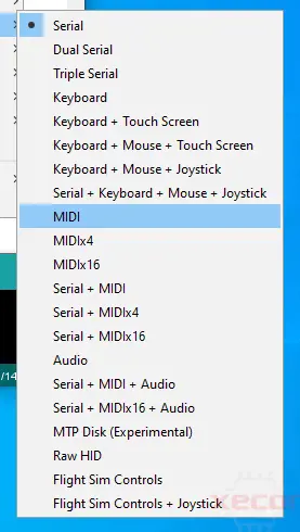
Tools > USB Type menu configures the type of USB device Teensy will implement.
- Serial - Recognized by your computer as a COM port (Windows) or serial device (Mac, Linux), Serial is the default and most commonly used communication type. Bytes are transferred in both directions at the maximum USB speed (baud rate settings are ignored). Teensyduino includes highly optimized code for fast USB serial data transfer. While typically used with the Arduino Serial Monitor, Teensy's USB Serial mode is compatible with software designed for serial ports, such as CoolTerm. On Teensy, the serial device is accessed as "Serial." In Dual & Triple Serial modes, the additional serial devices are "SerialUSB1" and "SerialUSB2".
- Emulated Serial—USB Type settings without Serial use an HID interface to emulate serial communication. In these modes, your PC or Mac will not detect a COM port or serial device, but you can still use Serial. Print () to send text to the Arduino Serial Monitor.
- MIDI - Musical Instrument Device. MIDI is often used to interface knobs, sliders, and buttons to music & sound control software. MIDI messages can be sent in both directions. Teensyduino's MIDI is "class compliant," ensuring compatibility with Macintosh, Linux, and Windows using only built-in drivers. The MIDIx4 & MIDIx16 modes provide 4 or 16 virtual MIDI ports/cables. The MIDI device name seen by your computer can be customized.
- Audio—Bidirectional stereo audio streaming, recognized by your computer as a USB sound card. Using your computer's sound preferences, programs that play sound can stream to Teensy, and programs that record or process sound can receive as if you were using a USB microphone. USB Audio is designed to be used with the Teensy Audio Library, allowing your computer's sound to integrate with any audio processing system you design on Teensy.
- Keyboard—This is a standard 104-key USB keyboard. Programs can transmit keystrokes to your computer, allowing you to control nearly any software. Media control keys (play, pause, volume, etc.) can also be used. The Tools > Keyboard Layout menu supports many non-US keyboard layouts.
- Mouse—Emulates a special USB mouse. It can send your computer the relative motion of a normal mouse and the absolute screen position, similar to a digitizer pen. Mouse buttons and a scroll wheel are also supported.
- Joystick—This type emulates a joystick/game controller with 6 axes (X, Y, Z, Zr, Slider1, Slider2), 32 buttons, and 1 hat switch. It is useful for controlling games or other software that responds to a joystick.
- Touchscreen - Emulates a touchscreen capable of detecting up to 10 finger positions.
- MTP Disk - Media Transfer, recognized by your computer as a phone or camera that shares files.
- Flight Sim - Allows integration with the X-Plane flight simulator software. Variables and controls within the simulator are linked to variables in your code running on Teensy.
- Raw HID - Allows communication of 64-byte messages with custom-written software on your computer.
Serial
Teensy 3.2 provides 3 serial ports for connecting serial devices, such as MIDI, GPS receivers, DMX lighting, ESP wireless modules, etc. All 3 serial ports are fully independent and can transfer data simultaneously. None are shared with USB (as is done on some Arduino boards). Serial1 & Serial2 include FIFOs for better performance at high-speed baud rates.
I2C
Teensy 3.2 has 2 ports for I2C (signals SDA & SCL), allowing connection to a wide variety of chips that use I2C communication. The Wire library is used for I2C. Each I2C chip connected to the same SDA/SCL wires needs a unique address. Multiple I2C ports allow you to use more than 1 chip with the same address easily. All I2C ports support speeds of 100, 400, and 1000 kbit/sec.
SPI
Teensy 3.2 provides 1 port for SPI (signals MOSI, MISO, SCK), allowing connection to higher-speed chips, SD cards, and displays that use SPI communication. The SPI library provides software support for SPI. A FIFO is included for higher sustained speed transfers. Each SPI chip requires a chip select (CS) signal. Most libraries using SPI can use any digital pin. The SPI ports provide special hardware-controlled CS pins, which specially optimized libraries use for higher performance.
CAN
Teensy 3.2 has 1 port for CAN bus, allowing connection to automotive & industrial control systems that use CAN communication. A CAN transceiver chip must be added to complete the electrical interface between Teensy 3.2 and the CAN bus.
Special Functions of Pins
Input/Output:
The Teensy 3.2 offers 34 GPIO pins with a current sink/source capacity of 10mA, and the pins can have pullup resistors enabled.
Most pins also have additional functionality:
- Serial ports - for receiving and transmitting data using the UART protocol.
- I2C ports - for two-wire communication using the IIC protocol with the Wire library.
- SPI - for fast serial communication with the SPI library.
- PWM - for outputting an 8-bit pulse width modulated square wave, controlled using two functions:
- analogWrite() - for setting the duty cycle of the PWM waveform.
- analogWriteResolution() - for changing the PWM resolution from 2 bits to 16 bits.
- Analog pins can be controlled using three functions:
- analogRead() - for reading an integer value corresponding to the analog input.
- analogReference() - for selecting a reference voltage source for the ADC.
- analogReadResolution() - for configuring the resolution of the ADC conversion.
- Touch sensing pins - for capacitive touch sensing, controlled using the touchpad () function.
- Pin 13 features a built-in LED.
These special functions and their corresponding pins are depicted in the above pin diagram for Teensy 3.2.
TEENSY 3.2 Features
- Equipped with a 12-bit DAC for precise voltage level generation
- Includes 16 direct memory access controllers for immediate access by 64 request sources
- Features a cyclic redundancy check for rapid error detection
- Incorporates a 32 kHz oscillator for Real-Time Clock functionality
- Offers 8 different timers for various delay requirements
- Integrates an I2S (Inter-IC-Sound) interface for connecting audio devices for pulse code-modulated data transmission
- Includes a watchdog and JTAG (Joint Test Action Group) interface
- Provides a human-machine interface for ease of use and authentic accessibility
- Each microcontroller unit chip has a unique identification number for security purposes.
TEENSY 3.2 Specifications
|
Type |
Value |
|
Microcontroller |
MK20DX256 |
|
Operating voltage |
3.3V |
|
Recommended input voltage for VIN pin |
3.6V to 6.0V |
|
Analog inputs |
21 |
|
Digital I/O pins |
34 |
|
DC source/sink from I/O pins |
10mA |
|
Flash memory |
256KB |
|
SRAM |
64KB |
|
EEPROM |
2KB |
|
Frequency (clock speed) |
72MHz |
|
Communication |
I2C, SPI, UART, CAN, USB |
How to Power Teensy 3.2 Development Board
There are three methods to power your Teensy 3.2 development board:
- Use the built-in USB micro connector.
- Supply a voltage of 3.6V to 6V from an external source, such as a 5V regulator. This method is recommended.
- Supply 3.3V directly to the 3.3V pin. This method is not recommended because the supply line is directly connected to the microcontroller, and any spikes or ripples could potentially cause damage.
How to Program Teensy 3.2
To program the Teensy 3.2, you can use either a C editor or the Arduino software. However, the latter is often preferred by beginners due to its ease of use and quick setup.
You can download the Arduino software from the following link:
After downloading and installing the software, connect the Teensy 3.2 to your computer using the USB micro port.
Uploading Your First Program:
In the Arduino software, go to Tools > Boards and select "Teensy 3.2" from the menu. Then, under Tools > Ports, choose the correct COM port.
Since the built-in LED on the Teensy 3.2 is located on pin 13, similar to Arduino boards, you can use the basic blink sketch. The code is provided below.
void setup() {
pinMode(13, OUTPUT); // sets the digital pin 13 as output
}
void loop() {
digitalWrite(13, HIGH); // sets the digital pin 13 on
delay(1000); // waits for a second
digitalWrite(13, LOW); // sets the digital pin 13 off
delay(1000); // waits for a second
}
Add Teensyduino Add-on to Arduino IDE
To program the TEENSY 3.2 development board with the Arduino IDE, follow these steps:
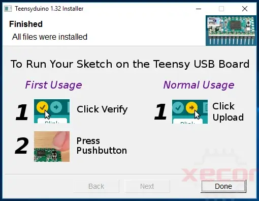
- Download the add-on from the following link: [download Teensyduino]. The add-on is available for Linux, Windows, and macOS. Download the Teensyduino version that matches your operating system and install it. The Teensyduino installer will add all the necessary files for the Teensy development board to be used with the Arduino IDE.
- After the add-on is successfully installed, you will see a screen similar to this. Click on the "Done" button.
- Open your Arduino IDE and select "Teensy" from the "Tools > Boards" menu.
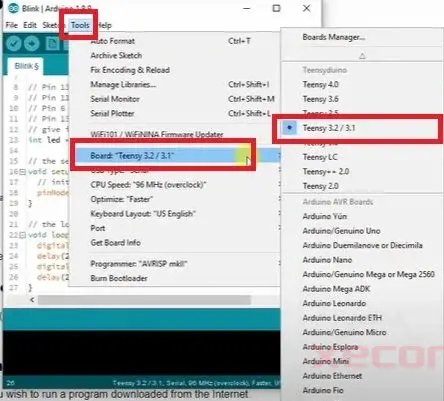
- Open the LED Blinking example. To upload a program to TEENSY's MCU, select the "TEENSY 3.2" board from the "Tools" menu and select the communication port through which the code/sketch will be uploaded to the microcontroller unit. Most programs created are compatible with TEENSY. To verify compatibility, upload the Blink Sketch and observe the built-in LED, which is labeled as D13, on the board.
TEENSY 3.2 Development Board Application
The TEENSY 3.6 development board is a powerful and versatile platform used in a variety of applications due to its high processing power and advanced features. Here's an expanded description of its applications:
Rapid Prototyping:
- The TEENSY 3.6 development board is widely used for rapid prototyping of electronic systems and projects.
- Its fast processor and extensive peripheral support make it ideal for quickly implementing and testing new ideas and concepts.
Hardware-Accelerated Cryptography:
- The TEENSY 3.6 development board features hardware-accelerated cryptography support, making it suitable for applications requiring secure communication and data encryption.
- Its cryptographic capabilities enable developers to implement secure communication protocols and data encryption algorithms with ease.
Robotics:
- In robotics applications, the TEENSY 3.6 development board is used for controlling and coordinating various robotic systems.
- Its high processing power and real-time capabilities make it ideal for tasks such as processing sensor data, motor control, and decision-making in robotics.
LED Strips:
- LED strips often use the TEENSY 3.6 development board due to its high processing power and direct memory access (DMA) capabilities.
- The board can efficiently control and manage LED strips, allowing for complex lighting effects and patterns to be easily implemented.
GPS Receivers and ESP WiFi Modules:
- The TEENSY 3.6 development board is commonly used with GPS receivers and ESP WiFi modules for various applications.
- Its compatibility with these modules allows for the development of location-based services, IoT devices, and other wireless communication systems.
Teensy 3.2 Development Board Datasheet
Download Teensy 3.2 Development Board Datasheet.
Teensy 3.2 vs. Arduino Uno
| Feature | Teensy 3.6 | Arduino Uno |
| Processor | MK20DX256 (ARM Cortex-M4) | Atmega328P (AVR) |
| Architecture | 32-bit | 8-bit |
| CPU speed | 72MHz | 16MHz |
| Flash Memory | 256 KB | 32 KB |
| Operating/input voltage | 3.3V | 5V |
| Analog pins | 21 | 8 |
| Digital IO/PWM | 34 | 14 |
| EEPROM/SRAM(KB) | 2/64 | 1/2 |
| USB Connector | Micro | Mini |
| UART | 3 | 1 |
| SPI | 2 | 1 |
| I2C | 3 | 1 |
| Price | Typically lower | Typically higher |
Teensy 3.2 offers a more powerful ARM Cortex-M4 processor with higher clock speed, more flash memory, and more I/O pins compared to Arduino Uno. However, Arduino Uno is simpler to use, has a larger user base, and may be more suitable for beginners.
Teensy 3.0 vs. Teensy 3.2& 3.1
| Feature | Teensy 3.0 | Teensy 3.2 Teensy 3.1 |
|---|---|---|
| Price | Typically lower | Typically higher |
| Processor | MK20DX128VLH5 | MK20DX256VLH7 |
| Core | Cortex-M4 | Cortex-M4 |
| Rated Speed | 48 MHz | 72 MHz |
| Overclockable | 96 MHz | 96 MHz |
| Flash Memory | 128 kbytes | 256 kbytes |
| Bandwidth | 96 Mbytes/sec | 192 Mbytes/sec |
| Cache | 32 Bytes | 256 Bytes |
| RAM | 16 kbytes | 64 kbytes |
| EEPROM | 2 kbytes | 2 kbytes |
| Direct Memory Access | 4 Channels | 16 Channels |
| Digital I/O | 34 Pins | 34 Pins |
| Voltage Output | 3.3V | 3.3V |
| Voltage Input | 3.3V Only | 5V Tolerant |
| Analog Input | 14 Pins | 21 Pins |
| Converters | 1 | 2 |
| Resolution | 16 Bits | 16 Bits |
| Usable | 13 Bits | 13 Bits |
| Prog Gain Amp | 0 | 2 |
| Touch Sensing | 12 Pins | 12 Pins |
| Comparators | 2 | 3 |
| Analog Output | 0 Pins | 1 Pins |
| DAC Resolution | - | 12Bits |
| Timers | 11 Total | 12 Total |
| FTM Type | 2 | 3 |
| PWM Outputs | 10 Pins | 12 Pins |
| PDB Type | 1 | 1 |
| CMT (infrared) Type | 1 | 1 |
| LPTMR Type | 1 | 1 |
| PIT (interval) Type | 4 | 4 |
| Systick | 1 | 1 |
| RTC (date/time) ** | 1 | 1 |
| USB | 1 | 1 |
| Serial | 3 | 3 |
| With FIFOs | 1 | 2 |
| High Res Baud | 3 | 3 |
| Fast Clock | 2 | 2 |
| SPI | 1 | 1 |
| With FIFOs | 1 | 1 |
| I2C | 1 | 2 |
| CAN Bus | 0 | 1 |
| I2S Audio | 1 | 1 |
| FIFO Size | 4 | 8 |
Teensy 3.1 and 3.2 offer significant improvements over the 3.0 model, including higher clock speeds, more flash memory, and more I/O pins, making them more capable for a wider range of projects.
Conclusion
In conclusion, the TEENSY 3.2 development board offers a powerful and versatile platform for a wide range of embedded projects. With its 32-bit ARM Cortex-M4 processor, ample memory, and support for various peripherals, the TEENSY 3.2 is capable of handling demanding tasks while remaining compact and energy-efficient. Its compatibility with the Arduino IDE and shields makes it easy to get started, even for beginners. Overall, the TEENSY 3.2 is a great choice for anyone looking to create innovative and feature-rich embedded systems.
Read More
FAQ
-
How many digital and analog pins does TEENSY 3.2 have?
TEENSY 3.2 has 34 digital pins, of which 21 can also be used as analog inputs.
-
What is the maximum current output of TEENSY 3.2?
The maximum current output of TEENSY 3.2 depends on the power source and the specific pins used. Generally, it can provide up to 250mA per pin and a total of 1A for all pins combined.
-
Is the TEENSY 3.2 compatible with the Arduino IDE?
Yes, the TEENSY 3.2 is fully compatible with the Arduino IDE. You can use the Arduino software to write and upload code to the board, making it easy to get started with programming.
-
What are the advantages of using TEENSY 3.2 over other development boards?
The TEENSY 3.2 offers several advantages, including its powerful ARM Cortex-M4 processor, ample flash and RAM, and support for a wide range of peripherals. It also has a compact size and low power consumption, making it ideal for embedded projects.
-
Can I use shields designed for Arduino with the TEENSY 3.2?
Yes, the TEENSY 3.2 can be used with shields designed for Arduino. The board is pin-compatible with Arduino shields, making it easy to expand its functionality using existing Arduino accessories.
-
How do I choose the right TEENSY 3.2 pins for my project?
When choosing pins for your project, consider the requirements of your components and the functionality you need. Refer to the pinout diagram and datasheet for TEENSY 3.2 to determine which pins are suitable for your specific needs.
Still, need help? Contact Us: [email protected]