Understanding the BeagleBone Black Pinout: Pin Diagram and Configuration Explained
 Prof. David Reynolds
Published:April 18, 2024
The BeagleBone Black (BBB) resembles a compact computer, featuring a processor, graphics acceleration, memory, and all necessary ICs soldered onto a single circuit board, making it a Single-Board Computer (SBC). Powered by a 1GHz AM335x ARM Cortex-A8 processor, it offers a cost-effective, community-supported development platform for developers and hobbyists. It boots Linux in under 10 seconds and allows development to start in less than 5 minutes with a single USB cable, providing a quick and easy setup.
This versatile microcontroller board can connect to a display, speakers, Ethernet network, keyboard, and mouse. It can also run a Linux operating system, making it an ideal tool for hobbyists and researchers to create advanced projects and explore Linux-based operating systems.
As a popular single-board computer, the BeagleBone Black has garnered significant attention for its versatility and robust features. Central to its functionality is its pinout, a crucial aspect for anyone looking to explore its capabilities fully. Understanding the pinout of the BeagleBone Black is essential for connecting peripherals, interfacing with sensors, and developing various projects in the embedded systems domain. This article aims to provide a comprehensive guide to the BeagleBone Black pinout, detailing its various pins, functions, and usage scenarios. By the end of this article, you will have a clear understanding of how to harness the power of the BeagleBone Black for your projects.

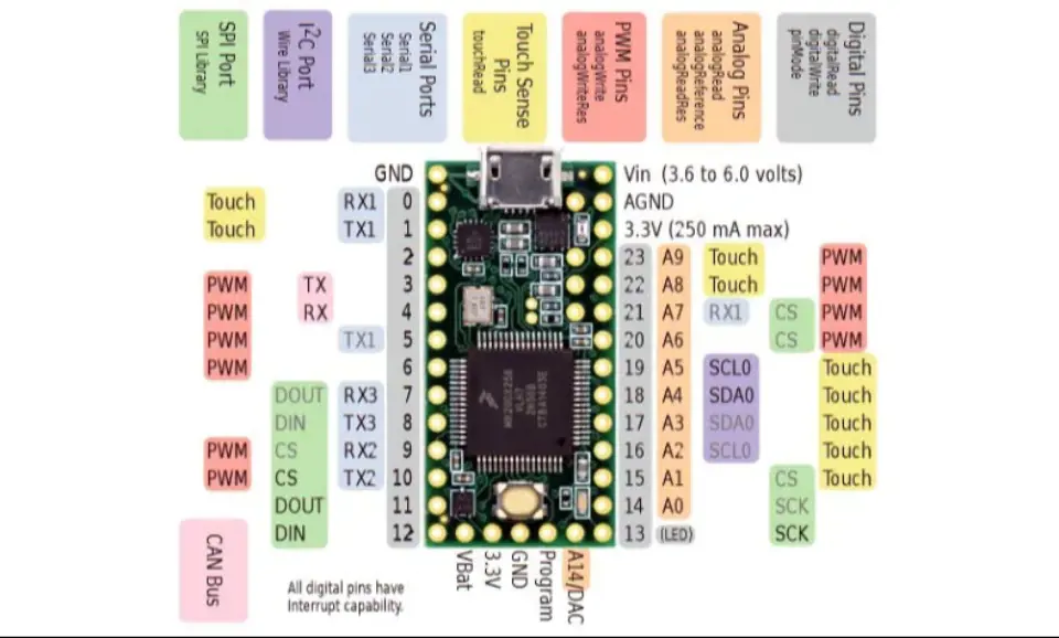
BeagleBone Black Pinout
The following figure is the BeagleBone Black pin diagram:

Types of Pins on the BeagleBone Black
Power Pin BeagleBone Black
The BeagleBone Black features two expansion headers, P8 and P9, each providing 46 pins for 3.3V I/O signals. Applying 5V to any pin can damage the board.
Power Input: The BeagleBone Black accepts power through a DC power jack and a USB port, each with different power input ratings.
Power Output: The board offers three power output pins for external devices:
- The first pin provides 3 volts, sourced directly from the Low Dropout Regulator (LDO), suitable for devices with a maximum current rating of 250mA. For higher-current devices, an external power source is recommended.
- The second power port provides 5 volts and is directly connected to the DC jack power supply pin. No power is present on this pin when the device is powered via USB. The current on this pin depends on the DC power input but is limited to 1000mA.
- The third power port utilizes a regulator and receives power from both USB and DC inputs. The voltage is 5 volts, but the current depends on the power input.
All these power pins are available in multiple locations:
In P9:
- +3.3V – Pin 3, Pin 4
- +5V (VDD) – Pin 5, Pin 6
- +5V (SYS) – Pin 7, Pin 8
Ground: Multiple ground pins are necessary for proper operation, and BeagleBone Black provides several interconnected ground pins for peripherals:
- In P8:
DGND – Pin 1, Pin 2, Pin 43, Pin 44, Pin 45, Pin 46
- In P9:
DGND – Pin 1, Pin 2
Power Button: The board includes a power button to safely shut down the device by saving all data. The power button is located in the P9 expansion header:
- PWR_BUT – Pin 9
Reset Button: An external reset button restarts the device safely. The reset button is located in the P9 header:
- SYS_RESETN – Pin 10
GPIO Pins BB
Digital Input/Output: The device offers 69 I/O pins, with the remaining pins reserved for other predefined functions. These I/O pins operate at 3.3 volts. The following table lists all the I/O pins available on the BeagleBone Black.
| In P8 header | In P9 header |
|
|
BB UART Communication Pins
It is one of the most popular serial communication protocols used in various systems and devices. In this communication method, separate pins are dedicated to transmitting and receiving data. The BeagleBone Black features multiple UART communication systems, with each of them listed below:
In P8:
- UART5_TX – Pin37
- UART_RX – Pin38
In P9:
- UART1_TX – Pin24
- UART1_RX – Pin26
- UART2_TX – Pin21
- UART2_RX – Pin22
- UART4_TX – Pin11
- UART4_RX – Pin13
SPI Communication Channel Pins
There are two SPI communication pins on the BeagleBone Black, each with a separate enslaved person selected. This allows each device to communicate with two different SPI protocol devices. Both SPI communication pins are located in Expansion Header P9:
- SPI0_CS0 – Pin17
- SPI0_D0 – Pin21
- SPI0_D1 – Pin18
- SPI0_SCLK – Pin22
- SPI1_CS0 – Pin28
- SPI1_D0 – Pin29
- SPI1_D1 – Pin30
- SPI1_SCLK – Pin31
I2C Communication Channels BeagleBone Black
Another serial communication system used by some sensors and servos is I2C. In the BeagleBone, there are two I2C communication pairs, all located in the P9 Expansion Header:
- I2C1_SCL – Pin17
- I2C1_SDA – Pin18
- I2C2_SCL – Pin19
- I2C2_SDA – Pin20
PWM Channel Pins
The BeagleBone Black can generate square pulses to control motors or other operable devices. It features multiple PWM pins that utilize internal timers and preschoolers to generate the output signal. All PWM pins are listed below:
In P8:
- PWM0A – Pin22
- PWM0B – Pin21
- PWM0A – Pin31
- PWM0B – Pin29
- PWM1A – Pin14
- PWM1B – Pin16
- ECAPPWM0 – Pin42
- ECAPPWM2 – Pin28
In P9:
- PWM1A – Pin36
- PWM1B – Pin34
- PWM2A – Pin45
- PWM2B – Pin46
- PWM2A – Pin19
- PWM2B – Pin13
ECAP-PWM: These pins are designated for generating PWM signals but can also be configured to accept PWM input signals. PWM is utilized to determine the frequency and duty cycle of an external device. The ECAPPWM pins on the BeagleBone Black are limited in number, and their locations are listed below:
In P9:
- ECAPPWM0 – Pin 42
- ECAPPWM2 – Pin 28
MCASP Pins
It is a port used for multi-channel serial applications. It uses separate clock, data, and frame sync pins. In the BeagleBone, the MCASP pins are located in the P9 Header, as shown below:
- MCASP0_FSX (Frame Sync) – Pin29
- MCASP0_ACLKX (Clock Sync) – Pin25
- MCASP0_AHCLKX (Data Out) – Pin31
- MCASP0_AXR2 (Data In) – Pin28
MMC Support Pins BeagleBone Black
It stands for Multimedia Card/SD Card Association (MMCA). In the BeagleBone Black, there is an embedded 2GB eMMC (embedded MultiMediaCard) that allows the device to boot from the built-in eMMC instead of an SD card. The eMMC is the default boot mode directly connected to the processor port. However, in the case of an SD card, the default mode will not be used because the eMMC is 8-bit and requires specific pins to operate. The third MMC, MMC2, will be used by other modules, as only MMC1 has external pins for operation. All MMC1 pins are located in Header P8.
- MMC1_CMD – Pin20
- MMC1_CLK – Pin21
- MMC1_DAT0 – Pin25
- MMC1_DAT1 – Pin24
- MMC1_DAT2 – Pin5
- MMC1_DAT3 – Pin6
- MMC1_DAT4 – Pin23
- MMC1_DAT5 – Pin22
- MMC1_DAT6 – Pin3
- MMC1_DAT7 – Pin4
BB HDMI LCD Interface Pins
The BeagleBone can be utilized to drive an LCD through HDMI. However, some pins dedicated to the HDMI framer are repurposed for other functions. Therefore, if these pins are used for other purposes, the framer will operate differently than expected since these pins are intended for input signals. All these pins are located in Expansion Header P8, listed below:
- LCD_VSYNC – Pin27
- LCD_PCLK – Pin28
- LCD_HSYNC – Pin29
- LCD_AC_BIAS – Pin30
- LCD_DATA14 – Pin31
- LCD_DATA15 – Pin32
- LCD_DATA13 – Pin33
- LCD_DATA11 – Pin34
- LCD_DATA12 – Pin35
- LCD_DATA10 – Pin36
- LCD_DATA8 – Pin37
- LCD_DATA9 – Pin38
- LCD_DATA6 – Pin39
- LCD_DATA7 – Pin40
- LCD_DATA4 – Pin41
- LCD_DATA5 – Pin42
- LCD_DATA2 – Pin43
- LCD_DATA3 – Pin44
- LCD_DATA0 – Pin45
- LCD_DATA1 – Pin46
Analog to Digital Converter Channels
In the BeagleBone, analog signals can be directly converted to digital signals. It features a total of 7 A/D channels, all utilizing a single 12-bit ADC channel that must be activated first by providing 1.8V power through the ADC power pins. All ADC channels and power pins are located in expansion header P9, listed below:
- AIN0 – Pin39
- AIN1 – Pin40
- AIN2 – Pin37
- AIN3 – Pin38
- AIN4 – Pin33
- AIN5 – Pin36
- AIN6 – Pin35
- VDD_ADC – Pin32
- GND_ADC – Pin34
BeagleBone Timers Modules Pins
Timers are essential for many external devices. The BeagleBone Black provides four internal timers that can be utilized based on the external pulse input pins. All these pins are located in P8, as listed below:
- TIMER1 – Pin10
- TIMER2 – Pin9
- TIMER4 – Pin7
- TIMER7 – Pin8
BeagleBone Black Pin Configuration
Each digital I/O pin offers 8 different modes, including GPIO. The tables below show the pinouts for the BeagleBone Black's P8 and P9 expansion headers.
The PROC column indicates the PIN on the processor.
The MODE columns display the various mode settings available for each pin.
Note that MODE5 is excluded because it does not serve any function. The only pin that operates in MODE5 is GPIO0_7 in expansion header P9, which can be set as mmc0_swdp.

Expansion Header P8 Pinout
| PIN | PROC | NAME | MODE0 | MODE1 | MODE2 | MODE3 | MODE4 |
| 1,2 | GND | ||||||
| 3 | R9 | GPIO1_6 | gpmc_ad6 | mmc1_dat6 | |||
| 4 | T9 | GPIO1_7 | gpmc_ad7 | mmc1_dat7 | |||
| 5 | R8 | GPIO1_2 | gpmc_ad2 | mmc1_dat2 | |||
| 6 | T8 | GPIO1_3 | gpmc_ad3 | mmc1_dat3 | |||
| 7 | R7 | TIMER4 | gpmc_advn_ale | timer4 | |||
| 8 | T7 | TIMER7 | gpmc_oen_ren | timer7 | |||
| 9 | T6 | TIMER5 | gpmc_be0n_cle | timer5 | |||
| 10 | U6 | TIMER6 | gpmc_wen | timer6 | |||
| 11* | R12 | GPIO1_13 | gpmc_ad13 | lcd_data18 | mmc1_dat5* | mmc2_dat1 | eQEP2B_in |
| 12* | T12 | GPIO1_12 | gpmc_ad12 | lcd_data19 | mmc1_dat4* | mmc2_dat0 | eQEP2B_in |
| 13* | T10 | EHRPWM2B | gpmc_ad9 | lcd_data22 | mmc1_dat1* | mmc2_dat5 | eQEP2B_in |
| 14* | T11 | GPIO1_26 | gpmc_ad10 | lcd_data21 | mmc1_dat2* | mmc2_dat6 | ehrpwm_tripzone |
| 15* | U13 | GPIO1_15 | gpmc_ad15 | lcd_data16 | mmc1_dat7* | mmc2_dat3 | eQEP2_strobe |
| 16* | V13 | GPIO1_14 | gpmc_ad14 | lcd_data17 | mmc1_dat6* | mmc2_dat2 | eQEP2_index |
| 17* | U12 | GPIO1_27 | gpmc_ad11 | lcd_data20 | mmc1_dat3* | mmc2_dat7 | ehrpwm0_synco |
| 18* | V12 | GPIO2_1 | gpmc_clk_mux0 | lcd_memory_clk | gpmc_wait1 | mmc2_clk | |
| 19* | U10 | gpmc_ad8 | gpmc_ad8 | lcd_data23 | mmc1_dat0* | mmc2_dat4 | ehrpwm2A |
| 20* | V9 | GPIO1_31 | gpmc_csn2 | gpmc_be1n | mmc1_cmd* | ||
| 21* | U9 | GPIO1_30 | gpmc_csn1 | gpmc_clk | mmc1_clk* | ||
| 22* | V8 | GPIO1_5 | gpmc_ad5 | mmc1_dat5 | |||
| 23* | U8 | GPIO1_4 | gpmc_ad4 | mmc1_dat4 | |||
| 24* | V7 | GPIO1_1 | gpmc_ad1 | mmc1_dat1 | |||
| 25* | U7 | GPIO1_0 | gpmc_ad0 | mmc1_dat0 | |||
| 26* | V6 | GPIO1_29 | gpmc_csn0 | ||||
| 27* | U5 | GPIO1_22 | lcd_vsync* | gpmc_a8 | |||
| 28* | V5 | GPIO1_24 | lcd_pcik* | gpmc_a10 | |||
| 29* | R5 | GPIO1_23 | lcd_hsync* | gpmc_a9 | |||
| 30* | R6 | GPIO1_25 | lcd_ac_bias_en* | gpmc_a11 | |||
| 31* | V4 | UART5_CTSN | lcd_data14* | gpmc_a19 | eQEP1_index | mcasp0_axr1 | uart5_rxd |
| 32* | T5 | UART5_RTSN | lcd_data15* | gpmc_a19 | eQEP1_strobe | mcasp0_ahclkx | mcasp0_axr3 |
| 33* | V3 | UART4_RTSN | lcd_data13* | gpmc_a17 | eQEP1B_in | mcasp0_fsr | mcasp0_axr3 |
| 34* | U4 | UART3_RTSN | lcd_data11* | gpmc_a15 | ehrpwm1A | mcasp0_ahclkr | mcasp0_axr2 |
| 35* | V2 | UART4_CTSN | lcd_data12* | gpmc_a16 | ehrpwm1_tripzone | mcasp0_aclkr | mcasp0_axr2 |
| 36* | U3 | UART3_CTSN | lcd_data10* | gpmc_a14 | ehrpwm0_synco | mcasp0_axr0 | |
| 37* | U1 | UART5_TXD | lcd_data8* | gpmc_a12 | mcasp0_aclkx | uart5_txd | |
| 38* | U2 | UART5_RXD | lcd_data9* | gpmc_a13 | mcasp0_fsx | uart5_rxd | |
| 39* | T3 | GPIO2_12 | lcd_data6* | gpmc_a6 | eQEP2_index | pr1_edio_data_out | |
| 40* | T4 | GPIO2_13 | lcd_data7* | gpmc_a7 | eQEP2_strobe | ||
| 41* | T1 | GPIO2_10 | lcd_data4* | gpmc_a4 | eQEP2A_in | ||
| 42* | T2 | GPIO2_11 | lcd_data5* | gpmc_a5 | eQEP2B_in | ||
| 43* | R3 | GPIO2_8 | lcd_data2* | gpmc_a2 | ehrpwm2_tripzone | ||
| 44* | R4 | GPIO2_9 | lcd_data3* | gpmc_a3 | ehrpwm_synco | ||
| 45* | R1 | GPIO2_6 | lcd_data0* | gpmc_a0 | ehrpwm2A | ||
| 46* | R2 | GPIO2_7 | lcd_data1* | gpmc_a1 | ehrpwm2B |
*some pins are used by internal storage eMMC (11-21) and HDMI (27-46)
Expansion Header P9 Pinout
| PIN | PROC | NAME | MODE0 | MODE2 | MODE3 | MODE4 |
| 1,2 | GND | |||||
| 3,4 | DC_3.3V | |||||
| 5,6 | VDD_5V | |||||
| 7,8 | SYS_5V | |||||
| 9 | PWR_BUT | |||||
| 10 | A10 | RESET_OUT | ||||
| 11 | T17 | gpmc_wait0 | mii2_crs | gpmc_csn4 | rmii2_crs_dv | mmc1_sdcd |
| 12 | U18 | gpmc_be1n | mii2_col | gpmc_csn6 | mmc_dat3 | gpmc_dir |
| 13 | U17 | gpmc_wpn | mii2_rxerr | gpmc_csn5 | rmii2_rxerr | mmc2_sdcd |
| 14 | U14 | gpmc_a2 | mii2_txd3 | rgmii2_td3 | mmc2_dat1 | gpmc_a18 |
| 15 | R13 | gpmc_a0 | gmii2_txen | rmii2_tctl | mii2_txen | gpmc_a16 |
| 16 | T14 | gpmc_a3 | mii2_txd2 | rgmii2_td2 | mmc2_dat2 | gpmc_a19 |
| 17 | A16 | spi0_cs0 | mmc2_sdwp | I2C1_SCL | ehrpwm0_synci | |
| 18 | B16 | spi0_d1 | mmc1_sdwp | I2CL_SDA | ehrpwm0_tripzone | |
| 19 | D17 | uart1_ctsn | timer5 | dcan0_rx | I2C2_SCL | spi1_cs1 |
| 20 | D18 | uart1_ctsn | timer6 | dcan0_tx | I2C2_SDA | spi1_cs0 |
| 21 | B17 | spi0_d0 | uart2_txd | I2C2_SCL | ehrpwm0B | |
| 22 | A17 | spi0_sclk | uart2_txd | I2C2_SDA | ehrpwm0A | |
| 23 | V14 | gpmc_a1 | gmii2_rxdv | rgmii2_rxdv | mmc2_dat0 | gpmc_a17 |
| 24 | D15 | uart1_txd | mmc2_swdp | dcan1_rx | I2C1_SCL | |
| 25 | A14 | mcasp0_ahclkx | eQEP0_strobe | mcasp0_axr3 | mcasp1_axr1 | EMU4_mux2 |
| 26 | D16 | uart1_rxd | mmc1_sdwp | mcasp0_axr2 | I2C1_SDA | |
| 27 | C13 | mcasp0_fsr | eQEP0B_in | mcasp1_fsx | EMU2_mux2 | |
| 28 | C12 | mcasp0_ahclkr | ehrpwm0_synci | spi1_cs0 | eCAP2_in_PWM2_out | |
| 29 | B13 | mcasp0_fsx | ehrpwm0B | spi1_d0 | mmc1_sdcd_mux1 | |
| 30 | D12 | mcasp0_axr0 | ehrpwm0_tripzone | spi1_d1 | mmc2_sdcd_mux1 | |
| 31 | A13 | mcasp0_aclkx | ehrpwm0A | spi1_sclk | mmc0_sdcd_mux1 | |
| 32 | ||||||
| 33 | C8 | |||||
| 34 | ||||||
| 35 | A8 | |||||
| 36 | B8 | |||||
| 37 | B7 | |||||
| 38 | A7 | |||||
| 39 | B6 | |||||
| 40 | C7 | |||||
| 41 | D14 | xdma_event_intr1 | tclkin | clkout2 | timer7_mux1 | |
| D13 | mcasp0_axr1 | eQEP0_index | mcasp1_axr0 | emu3 | ||
| 42 | C18 | eCAPO_in_PWM0_out | uart3_txd | spi1_cs1 | pr1_ecap0_ecap_capin_apwm_o | spi1_sclk |
| B12 | mcasp0_aclkr | eQEP0A_in | mcasp0_axr2 | mcasp1_aclkx |
- Up to 8 I/O pins can be configured with PWM (pulse width modulator) to generate signals for controlling motors without utilizing extra CPU cycles.
- Pins 32 to 40 in header P9 constitute a single 12-bit analog-to-digital converter with 8 channels.
- There are two I2C ports. The first I2C bus is typically used for reading EEPROMs but can also be used for other digital I/O operations without interference. The second I2C port is available for configuration based on user needs.
- The BeagleBone Black has 2 SPI ports for fast data shifting.
- For advanced users, the BeagleBone Black features 25 PRU (Programmable Real-time Unit) low latency I/Os. These can leverage 2 built-in 32-bit 200 MHz microcontrollers called PRUs for performing real-time tasks.
Features & Specifications
|
Type |
Parameter |
|
|
Processor |
Sitara AM3358BZCZ100 1 GHz, 2000 MIPS, AM335x with ARM Cortex-A8 processor |
|
|
Operating Voltage Range |
5V with 210-460mA |
|
|
Graphics Engine |
SGX530 3D, 20M Polygons/S |
|
|
SDRAM Memory |
512MB DDR3L 800 MHz |
|
|
Onboard Flash |
4GB, 8-bit Embedded MMC |
|
|
PMIC |
TPS65217C PMIC regulator and one additional LDO |
|
|
Debug Support |
Optional Onboard 20-pin CTI JTAG, Serial Header |
|
|
GPIO PORTS |
69 I/O Pins (but other can be used) |
|
|
Power Source |
miniUSB, USB or DC jack |
5V DC External Via Expansion Header |
|
PCB |
3.4” x 2.1” |
6 layers |
|
Indicators |
1-Power, 2-Ethernet, 4-User Controllable LEDs |
|
|
HS USB 2.0 Client Port |
Access to USB0, client mode via miniUSB |
|
|
HS USB 2.0 Host Port |
Access to USB1, Type A socket, 500 mA LS/FS/HS |
|
|
Serial Port |
UART0 access via 6-pin 3.3V TTL Header. Header is populated |
|
|
Ethernet |
10/100, RJ45 |
|
|
SD/MMC Connector |
microSD, 3.3V |
|
|
User input |
Reset button Boot button Power button |
|
|
Video out |
16b HDMI, 1280 x 1024 (MAX) 1024 x 768 x 1280 x 720, 1440 x 900, 1920 x 1080@24 Hz w/EDID Support |
|
|
Audio |
Via HDMI Interface, Stereo |
|
|
Expansion Connectors |
Power 5V, 3.3V, VDD_ADC(1.8V) 3.3V I/O on all signals McASP0, SPI1, I2C, GPIO(69 max), LCD, GPMC, MMC1, MMC2, 7 AIN(1.8V Max), 4 timers, 4 Serial Ports, CAN0, EHRPWM(0,2) , XDMA Interrupt, Power button, Expansion board ID (up to 4 can be stacked) |
|
|
LAN |
Available |
|
|
SD Card |
Available |
|
|
HDMI |
Available |
|
|
WIFI |
Not Available |
|
|
PWR Exp Header |
Not Available |
|
|
EEPROM |
512 bytes |
|
|
Weight |
39.68 grams (1.4 oz) |
|
BeagleBone Black Block Diagram

Where to Use BeagleBone Black?
The BeagleBone Black is commonly used as a cost-effective and compact development platform, well-supported by its growing community. It excels in physical computing and smaller embedded applications.
One of its standout features is the ability to add "capes," which are plug-in boards that enhance its functionality. Capes are available for motor control, VGA, camera, LCD, and other purposes.
The BeagleBone Black is particularly useful:
- When you need to run resource-intensive operating systems with low power consumption, the Arduino may fall short during certain DIY projects, especially during OS boot and heavy software execution. The BeagleBone Black performs these operations efficiently with low power consumption.
- When your project requires numerous hardware connections, the BeagleBone Black surpasses the Raspberry Pi in GPIO connectivity. While the Raspberry Pi offers a single 26-pin header for 8 GPIO pins or serial bus, the BeagleBone Black boasts two 48-socket headers, allowing for a vast number of I/O hardware connections. It also features several analog I/O pins for sensor connectivity, a feature lacking in the Raspberry Pi.
- When you need a quick project start-up, the BeagleBone Black boots up rapidly, thanks to its pre-installed Linux distribution. This saves considerable time and avoids unnecessary complications.
How to Get Started with BeagleBone Black?
Getting started with the BeagleBone Black is quick and easy. Follow these steps:
- Plug it into your computer using the included mini USB cable. This will power it up and boot it into its Linux distribution, Angstrom.
- Connect it to a display and USB peripherals.
- Install drivers to connect the BeagleBone Black to your web browser and control it with your computer.
- Explore the Linux operating system or write custom software for the BeagleBone Black using Python and libraries to manage all GPIOs.
BeagleBone Black Applications
Robotics:
- The BeagleBone Black is ideal for robotics applications, providing the necessary computing power and I/O capabilities for controlling robotic systems.
- Its small form factor and ample connectivity options make it suitable for integrating into robotic platforms, enabling advanced control and sensing capabilities.
Motor Controller:
- As a motor controller, the BeagleBone Black can interface with motor drivers to control the speed and direction of motors.
- Its GPIO pins and interface options make it suitable for implementing complex motor control algorithms, making it a valuable tool for motor control applications.
Controlling and Monitoring using Display Cape:
- With a compatible Display cape, the BeagleBone Black can be used for controlling and monitoring applications.
- The display cape provides a user-friendly interface for interacting with the BeagleBone Black, making it ideal for applications that require visual feedback and control.
Automation:
- In automation applications, the BeagleBone Black can be used to control and monitor various systems and processes.
- Its flexibility and connectivity options make it suitable for a wide range of automation tasks, from simple home automation projects to industrial automation applications.
IoT:
- The BeagleBone Black is well-suited for IoT (Internet of Things) applications, thanks to its connectivity options and processing power.
- It can collect sensor data, communicate with other IoT devices, and interface with cloud services, making it ideal for building IoT solutions.
AWS:
- The BeagleBone Black can be integrated with AWS (Amazon Web Services) to enable cloud connectivity for IoT applications.
- It can send data to AWS for processing and storage, enabling scalable and secure IoT solutions.
Bluetooth Connectivity Projects:
- For Bluetooth connectivity projects, the BeagleBone Black can be used to interface with Bluetooth modules and devices.
- Its capabilities make it suitable for implementing Bluetooth-based communication protocols for various applications, such as wireless data transfer and remote control.
What is the Difference Between BeagleBone Black and BeagleBone?
|
Feature |
Beaglebone Black |
Beaglebone |
|
Processor |
AM3358BZCZ100, 1GHz |
AM3359ZCZ72, 720 MHz |
|
Video Out |
HDMI |
None |
|
DRAM |
512 MB DDR3L, 800MHz |
256MB DDR2, 400MHz |
|
Flash |
4GB eMMC , uSD |
uSD |
|
Onboard JT |
Optical |
Yes, over USB |
|
Serial |
Header |
Via USB |
|
PWR Exp Header |
No |
Yes |
|
Power |
210-460 mA@5V |
300-500 mA@5V |
The BeagleBone Black features a faster processor, more RAM, HDMI video output, and onboard flash memory compared to the original BeagleBone. However, the original BeagleBone includes a power expansion header and a serial interface header, which are not present on the BeagleBone Black. Both boards are powered by the ARM Cortex-A8 processor, but the BeagleBone Black operates at a higher clock speed of 1GHz, while the original BeagleBone runs at 720MHz. Additionally, the BeagleBone Black has 512MB of DDR3 RAM, compared to 256MB of DDR2 RAM on the original BeagleBone.
BeagleBone Black 2D-Model and Dimensions

Conclusion
The BeagleBone Black is a versatile and powerful development board with a rich set of features and a well-documented pinout. Its pinout allows for flexible interfacing with a wide range of devices and sensors, making it suitable for a variety of projects, from simple electronics experiments to complex IoT applications. The BeagleBone Black's pinout, combined with its robust hardware and extensive software support, makes it a valuable tool for electronics enthusiasts, students, and professionals alike. In summary, the open-source Linux-like approach of the BeagleBone has bridged the gap between industrial computers and session border controllers (SBCs). This has facilitated increased exploration of artificial intelligence in various aspects of life, all with simple pre-installation tools.
Read More
FAQ
-
How many pins does BeagleBone Black have?
The BeagleBone Black features 65 general-purpose input/output (GPIO) pins split between two 46-pin headers, P8 and P9.
-
What are the analog inputs of BeagleBone Black?
The BeagleBone Black hardware includes six analog input pins (AIN0 to AIN5).
-
What voltage is the BeagleBone GPIO?
The GPIOs on the BBB are 3.3V tolerant. Each pin can only source 4-6 mA and sink about 8 mA.
-
Are there similar development boards for BeagleBone Black?
Raspberry Pi, Arduino Yun, ARM LPC2129, Intel Edison, and Beagle Bone Green.
-
Which is better, Raspberry Pi or BeagleBone?
The BeagleBone board offers more GPIO pins than the Raspberry Pi, making it better suited for developing embedded systems and IoT projects. However, the choice between the two boards depends on the specific application. If you find this information helpful, please share this post and leave your feedback in the comments.
Still, need help? Contact Us: [email protected]