DRV8825 vs. A4988: How to Choose the Right Stepper Driver Boards
 Prof. David Reynolds
Published:February 03, 2024
Stepper motor drivers play a crucial role in governing the precision and control of stepper motors by translating electrical pulses into accurate mechanical movements. Serving as a link between microcontrollers and stepper motors, these drivers significantly influence the motor's performance in terms of accuracy and smooth operation. The selection of an appropriate stepper motor driver holds immense importance as it directly impacts the compatibility, performance, and overall efficiency of a stepper motor system. A well-matched driver ensures optimal torque, speed, and reliability, thereby influencing the success of diverse applications ranging from 3D printers to CNC machines.
Within the domain of stepper motor drivers, the DRV8825 and A4988 emerge as noteworthy contenders, drawing widespread attention. These drivers come equipped with distinct features and advantages, making them the preferred choice among engineers, hobbyists, and professionals. In the article, we'll delve deeper into the differences between these drivers, exploring their features, functionalities, applications, etc and which might be the better choice for specific scenarios.
Overview of DRV8825
The DRV8825 serves as a stepper motor driver board equipped with the DRV8825 chip, allowing the control of stepper motors through Arduino-like programming firmware and software. Capable of delivering a peak output current of up to 2.5 A or an RMS output of 1.75 A (with appropriate heatsinking at 24 V and 25°C), the DRV8825 board is designed for efficient motor control.
Featuring two H-bridge drivers and a micro-stepping indexer, the DRV8825 stepper motor driver accommodates a broad voltage range, spanning from 8.2 V to 45 V. Its application extends to serving as an integrated motor driver for printers, scanners, and various automated equipment.

Overview of A4988
The A4988 stands as a comprehensive Microstepping Motor Driver featuring a built-in translator for user-friendly operation. Equipped with a translator and overcurrent protection, this driver supports a maximum output capacity of 35 V and ±2 A. It is proficient in driving bipolar stepper motors, offering operational modes in full, half, quarter, eighth, and sixteenth steps.
In the realm of controlling stepper motors, the A4988 stepper motor driver plays a vital role. Precise management of the current powering the motor coils ensures accurate and controlled motion. Its straightforward interface and seamless integration have positioned it as a favored choice across diverse applications, ranging from 3D printers to robotics.

DRV8825 vs. A4988: Orientation
DRV8825 Orientation
Certain DRV8825 stepper driver boards may have the trimpot positioned on a different edge of the PCB in comparison to A4988 boards. It is crucial to carefully observe the correct orientation of the stepper driver boards when placing them into the sockets on the controller board. Identify a labeled pin, such as DIR, GND, ENABLE, or VMOT, situated on one or more corners of the stepper driver board and align it with the corresponding pinouts on the RAMPS. Exercise caution, as some stepper boards might appear as mirror images of other boards of the same type, requiring verification of the pin labels. Avoid making assumptions about the placement of the trim pot at one end or the other of the board, for instance.
A4988 Orientation
Inserting an A4988 stepper driver incorrectly can result in its malfunction and potentially harm the RAMPS board when power is applied. Hence, be vigilant about the proper orientation of the stepper driver boards when placing them into their sockets on the controller board. Identify a labeled pin on one or more corners of the stepper driver board (such as DIR, GND, ENABLE, VMOT) and align it with the corresponding RAMPS pinouts. Keep in mind that certain stepper boards may appear as mirrored versions of others of the same type, so always confirm the pin labels. Avoid assuming that the trim pot consistently belongs to one end of the board or the other, for instance.
DRV8825 vs. A4988: Pinout
DRV8825 Pinout

A4988 Pinout

DRV8825 vs. A4988: Features
DRV8825 Features
- Maximum current rating of 2.5A.
- Supports a maximum of 32 subdivisions.
- Lower chip resistance for enhanced heat dissipation and reduced heat generation.
- Suitable for driving stepper motors with a voltage range of 8.2V to 45V and current below 2.5A.
- Features a straightforward step and direction control interface.
- Offers six different step resolutions: full-step, half-step, 1/4-step, 1/8-step, 1/16-step, and 1/32-step.
- An adjustable current control enables the setting of the maximum current output using a potentiometer, allowing the use of voltages higher than the stepper motor's rated voltage for increased step rates.
- Intelligent chopping control automatically selects the appropriate current decay mode (fast decay or slow decay).
- Supports a maximum supply voltage of 45V.
- The built-in regulator eliminates the need for an external logic voltage supply.
- Direct compatibility with 3.3V and 5V systems.
- It incorporates over-temperature thermal shutdown, over-current shutdown, cross-current protection, and under-voltage lockout for enhanced safety.
- Provides short-to-ground and shorted-load protection.
- Utilizes a 4-layer, 2 oz copper PCB for improved heat dissipation.
- Features an exposed solderable ground pad beneath the driver IC on the bottom of the PCB.
- Module size, pinout, and interface align with our A4988 stepper motor driver carriers in most aspects (refer to the bottom of this page for additional information).
A4988 Features
- Low RDS(ON) outputs for efficient performance.
- Synchronous rectification to minimize power dissipation.
- Compatible with 3.3V and 5V logic supply.
- Maximum operating voltage: 35V.
- Minimum operating voltage: 8V.
- Maximum current per phase: 2A.
- No reverse voltage protection.
- Straightforward step and direction control interface.
- Offers five different step resolutions: full-step, half-step, quarter-step, eighth-step, and sixteenth-step.
- Adjustable current control allows setting the maximum current output using a potentiometer, enabling the use of voltages exceeding the stepper motor's rated voltage to achieve higher step rates.
- Intelligent chopping control automatically selects the appropriate current decay mode (fast decay or slow decay).
- Includes over-temperature thermal shutdown, internal under-voltage lockout, and crossover-current protection for enhanced safety.
- Short-to-ground and shorted-load protection (this feature is not available on the A4983).
- Comes complete with a self-adhesive heat sink.
DRV8825 vs. A4988: Block Diagram
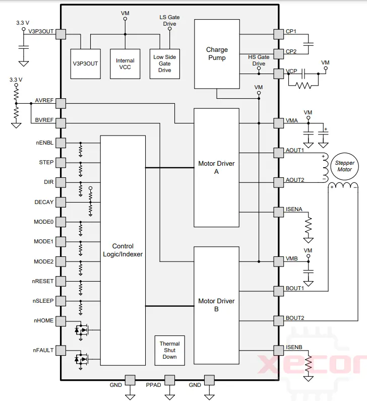
DRV8825 Block Diagram
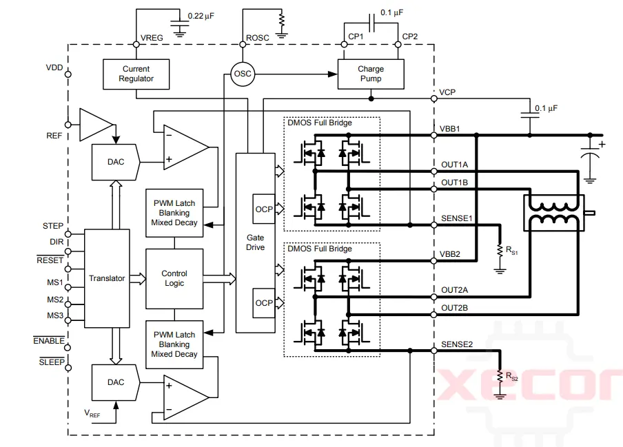
A4988 Block Diagram
DRV8825 vs. A4988: Schematic Diagram
DRV8825 Schematic Diagram

A4988 Schematic Diagram

DRV8825 vs. A4988: Control inputs
DRV8825 Control inputs
RESET, SLEEP, and ENBL represent the trio of inputs responsible for regulating the power states of the chip. Refer to the datasheet for comprehensive details regarding these power states. The SLEEP pin incorporates an internal 1M pull-down resistor to pull it low, whereas the RESET and ENBL pins utilize internal 100k pull-down resistors to achieve a low state. To activate the driver, both RESET and ENBL pins must be in a high state (they can be directly connected to a logic "high" voltage ranging from 2.2 to 5.25 V, or their status can be dynamically controlled through connections to digital outputs of an MCU). The default condition for the ENBL pin is to enable the driver, allowing this pin to remain unconnected if desired.
A4988 Control inputs
Every pulse applied to the STEP input initiates a movement of one micro-step in the direction indicated by the DIR pin for the stepper motor. It is crucial not to leave the STEP or DIR pins unconnected in your application as they lack internal pull to a specific voltage. If you desire rotation in only one direction, DIR can be directly linked to VCC or GND. The RST, SLP, and EN are the trio of inputs employed for regulating the chip's various power states. Refer to the datasheet for in-depth insights into these power states. It is important to note that the RST pin is floating; when not in use, connect it to the adjacent SLP pin on the PCB to set it high. If the pin is not utilized, connecting it to the nearby SLP pin on the PCB will set it high and activate the board.
DRV8825 vs. A4988: Using the Driver
DRV8825 Using the Driver

A4988 Using the Driver

DRV8825 vs. A4988: Applications
DRV8825 Applications
- Printers
- Scanners
- Robotics
- Gaming Machines
- Automatic Teller Machines
- Money Handling Machines
- Video Security Cameras
- Office Automation Machines
- Factory Automation
A4988 Applications
- 3D Printing
- Robotics
- CNC Machining
- Textile Machinery
- Security Cameras and Pan-Tilt Mechanisms
- Medical Equipment
- Educational and Hobbyist Projects
DRV8825 vs. A4988: Equivalent/Alternative
DRV8825 Equivalent/Alternative
A4988, NEMA 17, A498, L6474, L6207, L6208, TMC2208, and TMC2209.
A4988 Equivalent/Alternative
DRV8825, L6474, L6207, L6208, TMC2208 and TMC2209.
DRV8825 vs. A4988: Datasheet
DRV8825 Datasheet
A4988 Datasheet
DRV8825 vs. A4988: Package
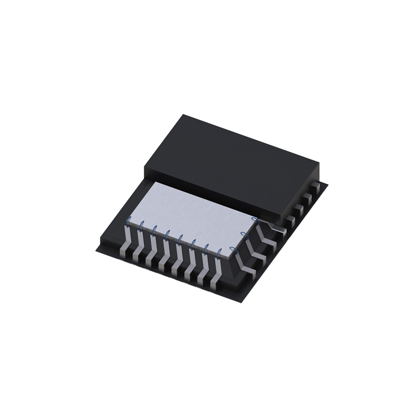
DRV8825 Package

A4988 Package

DRV8825 vs. A4988: What's the Difference?
- The pin used for supplying logic voltage to the A4988 serves as the FAULT output on the DRV8825, eliminating the need for a logic supply (the A4988 lacks a fault output). Directly connecting the FAULT pin to a logic supply is safe, with a protective 1.5k resistor.
- Unlike the A4988, the SLEEP pin on the DRV8825 is not pulled up by default. The carrier board connects it to the FAULT pin through a 10k resistor, creating a 10k pull-up on the SLEEP pin for systems designed for the A4988.
- The location of the current limit potentiometer differs.
- The relationship between the current limit setting and the reference pin voltage varies.
- The DRV8825 supports 1/32-step microstepping, while the A4988 only goes down to 1/16-step.
- Mode selection pin inputs corresponding to 1/16-step on the A4988 result in 1/32-step micro stepping on the DRV8825. For other micro-stepping resolutions, the step selection table is the same for both.
- Timing requirements for minimum pulse durations on the STEP pin differ between the two drivers. The DRV8825 demands at least 1.9 us for both high and low STEP pulses, while the A4988 accepts pulses as short as 1 us.
- The DRV8825 has a higher maximum supply voltage (45 V vs. 35 V) than the A4988, making it safer for use at higher voltages and less susceptible to damage from LC voltage spikes.
- The DRV8825 can deliver more current without additional cooling in full-step tests (1.5 A per coil for DRV8825 vs. 1.2 A per coil for A4988 Black Edition and 1 A per coil for the original A4988 carrier).
- The naming convention for stepper motor outputs differs on the DRV8825, but functionally, they are the same as the corresponding pins on the A4988 carrier. Both boards use the first part of the label to identify the coil.
- For those with color-sensitive applications, the DRV8825 carrier is purple.
DRV8825 vs. A4988: Comparison Table
| Feature | DRV8825 | A4988 |
| Microstepping Levels | 1, 1/2, 1/4, 1/8, 1/16, 1/32 | 1, 1/2, 1/4, 1/8, 1/16 |
| Maximum Current | Up to 2.5A | Up to 2A |
| Voltage Range | 8.2V to 45V | 8V to 35V |
| Logic Voltage | 3.3V or 5V | 3.3V or 5V |
| Typical Rs value | 0.1 Ohm | 0.05 Ohm or 0.1 Ohm or 0.2 Ohm |
| Vref formula (*) | I_TripMax= Vref/(5*Rs) | I_TripMax= Vref/(8*Rs) |
| PCB layers | 4 | 2 |
| PCB color | Purple | Green / Red |
| Stepper current adjust. trimpot | Adjustable | Yes, near Dir pin |
| Configuration Resistance | External potentiometer adjustment | External potentiometer adjustment |
| Built-in Protection | Over-temperature, Over-current, Short-circuit | Over-temperature, Over-current, Short-circuit |
| Step Pulse Timing | Adjustable | Fixed |
| Thermal Overload Protection (**) | Yes | Yes |
| Small heatsink included (***) | Sometimes not | Almost always |
| Heat Dissipation | Includes a heatsink | Requires external heatsink |
| Control Interface | Step and Direction | Step and Direction |
| Applications | 3D printers, CNC machines, robotics,etc. | 3D printers, CNC machines, robotics,etc. |
| Availability | widely available | very widely available |
| Cost | Generally higher | Generally lower |
| Active cooling required? | Recommended | Recommended |
| IC packaging | 9.7x6.4mm 28HTSSOP | 5x5mm 28-lead QFN |
It's important to note that certain crucial technical specifications from the individual IC datasheets cannot be directly juxtaposed. One instance is the comprehensive specification of thermal characteristics for the DRV8825, while the A4988 lacks such detailed specifications. Another significant characteristic that, regrettably, does not lend itself to a direct comparison is RDSon, as it is specified at distinct current levels in the respective IC datasheets.
DRV8825 vs. A4988: Which One Should I Choose?
In the comprehensive evaluation contrasting DRV8825 and A4988, the ultimate determination revolves around the distinctive requisites of one's project and the financial limitations therein. Should one find themselves attuned to the symphony of cost-effectiveness and dependability, the A4988 may assume a prominent position. Conversely, for those yearning for advanced functionalities, exacting precision, and the discreetly tranquil attributes of StealthChop, the DRV8825 may be perceived as a veritable paragon.
Conclusion
Numerous differences exist between the A4988 and DRV8825. The DRV8825 boasts 1/32-step microstepping capability, surpassing the A4988, which only achieves 1/16-step. Moreover, the DRV8825 accommodates a higher maximum supply voltage (45 V compared to 35 V), enhancing safety during operation at elevated voltages and reducing susceptibility to LC voltage spike damage. In addition, even without supplementary cooling, the DRV8825 demonstrates a superior current delivery compared to the A4988. Based on our full-step assessments, the DRV8825 achieves 1.5 A per coil, while the A4988 Black Edition achieves 1.2 A per coil, and the original A4988 carrier achieves 1 A per coil. Notably, due to the close resemblance of the DRV8825 carrier to our A4988 carriers, the A4988's minimal connection diagram remains applicable for connecting the DRV8825 to a microcontroller.
Read More

FAQ
-
What does A4988 do?
The A4988 serves as a micro-stepping driver for bipolar stepper motors, featuring an integrated translator for easy use. This means that managing the stepper motor only requires two pins from our controller – one for determining the rotation direction and the other for executing steps.
-
What does DRV8825 do?
The DRV8825 can handle a current output of up to 2.5 A per output (provided there is adequate heat dissipation, operating at 24 V and 25°C).
-
Are DRV8825 and A4988 interchangeable?
Both the A4988 and DRV8825 boards are interchangeable, depending on how they are installed and are expected to function similarly on any 3D printer or comparable system.
-
Which is better, A4988 or DRV8825?
The DRV8825 boasts a higher maximum supply voltage (45 V compared to 35 V), enhancing its safety when functioning at elevated voltages and reducing susceptibility to LC voltage spike damage.
-
Can I replace A4988 with TMC2209?
The TMC2209 exhibits optimal compatibility with the A4988, as the most notable adjustments can be finely tuned through pins.
-
What are the advantages of A4988?
The A4988 incorporates safeguards such as short-to-ground and short-load protection, complemented by thermal shutdown circuitry for the motor.
-
Can A4988 drive a DC motor?
Yes, you can run two DC motors of the A4988 module.
-
Why do I need a stepper driver?
Stepper motors demand precise and accurate control signals for accurate movement alongside a substantial supply of current and voltage for operation. The driver fulfills the crucial role of delivering both the requisite control signals and power amplification to propel the motor.
Still, need help? Contact Us: [email protected]