Comprehensive Explanation of the Modbus Communication Protocol
The Modbus protocol is a universal language used in electronic controllers, facilitating communication between controllers, networking via Ethernet, and interaction with other devices. It has become a widely adopted industrial standard, enabling control devices from different manufacturers to connect into industrial networks for centralized monitoring.
Transmission on Modbus Networks
The standard Modbus interface uses an RS-232C-compatible serial interface, defining pin connections, cables, signal levels, baud rates, and parity settings. Controllers can connect directly or through modems.
Communication in Modbus networks uses master-slave technology, where only one device (the master) can initiate transmissions (queries). Other devices (slaves) respond to data requests made by the master. Typical master devices include host computers and programmable instruments, while typical slave devices include programmable controllers.
A master device can communicate individually with slave devices or broadcast messages to all slaves. In individual communication, a response message is expected from the slave. In broadcast queries, no response is anticipated. The Modbus protocol defines the format for master device queries, including the device (or broadcast) address, function code, data to be sent, and error-checking field.
Slave devices respond with messages also structured by the Modbus protocol. These responses include an acknowledgment of the action to be taken, any data to be returned, and an error-checking field. If an error occurs during message reception or if a slave cannot execute the command, an error message is generated and sent as a response.
Transmission on Other Network Types
On other networks, controllers use peer-to-peer technology for communication, allowing any controller to initiate communication with other controllers. In such cases, controllers can act as either master or slave devices during individual communication processes. Multiple internal channels are provided to facilitate simultaneous transmission processes.
In terms of message structure, the Modbus protocol still adheres to the master-slave principle, even though network communication methods are peer-to-peer. If one controller sends a message, it is considered the master device and expects a response from the slave device. Likewise, when a controller receives a message, it constructs a slave device response format and returns it to the sending controller.
Query-Response Cycle
(1) Query
The function code in a query message informs the selected slave device of the desired action to perform. The data segment contains any additional information required for the slave device to execute the function. For example, function code 03 requests a slave device to read holding registers and return their contents. The data segment must include information for the slave device, such as which registers to start reading and how many registers to read. The error-checking field provides a means for the slave device to validate the message's content.
(2) Response
If the slave device generates a normal response, the function code in the response message corresponds to the function code in the query message. The data segment includes data collected by the slave device, such as register values or status. If an error occurs, the function code is modified in the response message to indicate that the response is erroneous, and the data segment includes a code describing the error. The error-checking field allows the master device to confirm the message's validity.
Two Transmission Modes
Controllers can be set to either of the two transmission modes (ASCII or RTU) in standard Modbus network communication. Users choose their preferred mode, including serial communication parameters (baud rate, parity, etc.). When configuring each controller, all devices on a Modbus network must select the same transmission mode and serial parameters.
(1) ASCII Mode
When a controller is configured to communicate in ASCII (American Standard Code for Information Interchange) mode on a Modbus network, each 8-bit byte in the message is transmitted as two ASCII characters. The primary advantage of this mode is that it allows a one-second character spacing without errors.
Code System:
Hexadecimal, ASCII characters 0...9, A...F
Each ASCII character in the message is represented as a hexadecimal character.
Bits per Byte:
1 start bit
7 data bits, with the least significant bit sent first
1 parity bit (optional)
1 stop bit (with parity) or 2 bits (without parity)
Error Checking Field:
LRC (Longitudinal Redundancy Check)
(2) RTU Mode
When a controller is configured to communicate in RTU (Remote Terminal Unit) mode on a Modbus network, each 8-bit byte contains two 4-bit hexadecimal characters. The main advantage of this mode is that it can transmit more data compared to ASCII mode at the same baud rate.
Code System:
8-bit binary, hexadecimal numbers 0...9, A...F
Each 8-bit field in the message consists of two hexadecimal characters.
Bits per Byte:
1 start bit
8 data bits, with the least significant bit sent first
1 parity bit (optional)
1 stop bit (with parity) or 2 bits (without parity)
Error Checking Field:
CRC (Cyclic Redundancy Check)
Wireless Modbus Implementation
By adhering to the Modbus communication protocol, it is possible to transform devices with RS-485/RS-232 interfaces into wireless Modbus communication devices. In other words, if wired Modbus network communication is working correctly, you only need to interface with hardware parameters compatible with the Modbus communication protocol through wireless modules (DTD433M/DTD434M/DTD435M/DTD418M/DTD419M) to achieve wireless Modbus network communication for multiple devices.
More Application-Related Electronic Components

MT41K512M8RH-125:E
DRAM Chip DDR3L SDRAM 4Gbit 512Mx8 1.35V 78-Pin FBGA
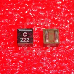
XGL4030-222MEC
2.2uH ±20% 7A 1616 Power Inductors ROHS

0900LP15B0063E
Ceramic Filters Low Pass 900MHz 0.9dB 50Ohm SMD 8Pin T/R
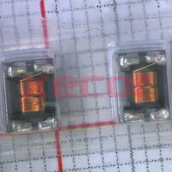
DLW43MH201XK2L
Common Mode Chokes Dual 200uH 100kHz 0.11A 4.5Ohm DCR SMD T/R Automotive AEC-Q200

Z0805C420APWST
Ferrite Beads Chip 42Ohm 25% 100MHz 4A 0.008Ohm DCR 0805 T/R
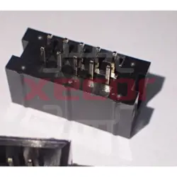
302-S101
Conn Shrouded Header (4 Sides) HDR 10 POS 2.54mm Solder ST Thru-Hole

PI3USB102GZLEX
High performance USB switch for device connectivity
SBH21-NBPN-D07-ST-BK
2 Gold 2mm -40℃~+105℃ Brass Straight Plugin Wire To Board / Wire To Wire Connector ROHS
READ ALSO
-
Rapidly Establishing a Local LoRaWAN Network Using LoRaWAN Gateways Date: 26/09/2023
LoRa modulation is a low-power, wide-area network communication technology, based on spread spectrum technology, developed by Semtech. LoRaWAN is a set of communication protocols and system architecture designed for long-range communication networks using LoRa technology. It functions as the Media Access Control (MAC) layer protocol.
-
Comprehensive Explanation of the Modbus Communication Protocol Date: 26/09/2023
The Modbus protocol is a universal language used in electronic controllers, facilitating communication between controllers, networking via Ethernet, and interaction with other devices. It has become a widely adopted industrial standard, enabling control devices from different manufacturers to connect into industrial networks for centralized monitoring.
-
MES System Collects PLC Data via OPC Intelligent Gateway Date: 25/09/2023
OPC is a common communication protocol in the industrial control field, used in devices such as PLCs, DCS, SCADA, and more. It enables interconnection and communication between industrial automation devices and can be integrated with other factory systems to enhance efficiency. Through the use of the物通博联 (Wu Tong Bolian) OPC intelligent gateway, MES (Manufacturing Execution System) can obtain real-time PLC data, enabling functions such as remote monitoring, remote control, and equipment management, thus assisting enterprises in creating a digital factory and information-based management.